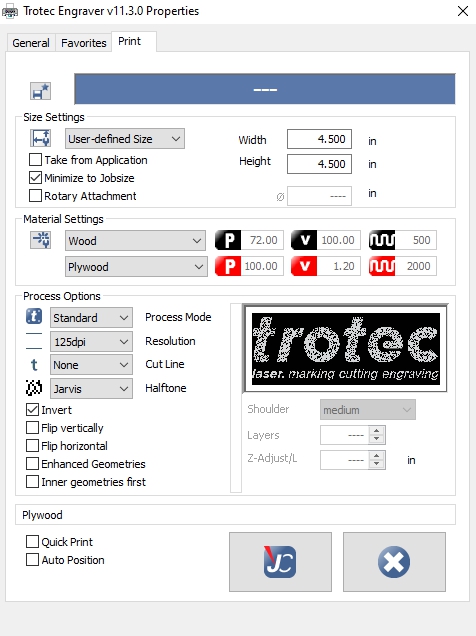
The Trotec property settings translate image information from your image-editing software into a set of instructions for the laser cutter. These settings are packaged with the image itself, and sent on to the Trotec Job control software as a “job”. Settings should be adjusted carefully to best suit each individual job; while some settings can be further adjusted in Job Control, others cannot. See below for an image of the properties window. The following sections provide a breakdown of each area in this window.

Size Settings
The size settings tell the laser cutter how much space your job will occupy on the bed. They will not change the scale of your job. Incorrect settings in this section can cause unwanted cropping.
User-Defined Size
This should be the default setting. The “Width” and “Height” boxes allow you to manually enter the size of your job.
Take from Application
Checking this box uses the size of your canvas or artboard in your image editing software as the size of the job. Selecting this setting greys out the opportunity to enter the job size manually
Minimize to Jobsize
Checking this box crops out any extra white space around your image so that it occupies the smallest amount of space possible. This modification is applied after the jobsize is specified (either manually, or taken from application)
N.B: The “Take from Application” checkbox does not work reliably with all image editing software. Often, any residual settings in the “Width” and “Height” boxes will override the size from the application, causing unwanted cropping. The safest course of action is to always enter the size of your image manually. “Minimize to Jobsize” works as intended.
N.B: The size settings cannot be changed in Job Control.
Material Settings
Material Settings adjust the power and speed of the laser based on the material you are engraving. A wide variety of material profiles are available. Choose the one that best represents the material you are working with. Each material setting contains an engraving setting in black and a cutting setting in red

- “P” indicates the Power of the laser, from 0 to 100%
- “V” indicates the Velocity of the engraving/cutting action, from 0 to 100%
- The wavy line indicated either Pulses Per Inch (when engraving) or Frequency when cutting.
N.B: The material setting, and its individual parameters, can be changed in Job Control.
N.B: For best results when engraving, ensure that the PPI of your material setting is a multiple of the resolution you choose in Process Options discussed below. For example, if you wish to engrave at 333 DPI, ensure that the PPI of your material setting is either 333 or 666. You will likely need to make this adjustment in job control. This is to ensure that the dots in your image’s halftone pattern line up with the individual engraving pulses of the laser.
Process Options
These settings determine how the image itself is modified in order to be engraved and or cut by the laser. It contains sections to determine both the treatment of the image, and the action of the laser. More information is available in the following sections.

Process Mode
This setting determined how colour and tone information in the image is translated into cutting and engraving pulses of the laser.
Standard/Photo-Optimized
What do they do?
Translates a grayscale image to a dithered black-and-white image using one of several Halftone Settings. Information on each halftone setting is provided below. Most of these settings produce the appearance of continuous tone through groupings of black and white dots, all of which are engraved to the same depth, using the full strength specified in Job Control.
When do I use them?
These are the default settings for engraving raster images. The choice between Standard and Photo-Optimized depends on the image, and may require testing to determine which produces the best results. Photo-Optimized tends to better preserve fine gradations of tone, while Standard emphasizes tonal shifts and edges. In general, Standard often produces better results for hand-drawn or similar imagery, while Photo-Optimized works best for photographic imagery.
Relief
What does it do?
The Relief setting translates the grayscale value of the image to the strength of the laser, relative to the Power setting specified in Job Control. 100% gray (black) will engrave at the full strength specified; 50% gray will engrave at half of the strength specified, and so on. This produces engraving at variable depth, with the ability to create smooth transitions in depth.
When do I use it?
When creating sculptural relief. This setting usually requires multiple passes at different settings to produce the best results, particularly when engraving wood. Trotec recommends 2-3 passes at high power and low speed for engraving, followed by 1-2 passes at medium power and high speed to clean the engraved surface of scorch marks or other burn residue. Actual settings will vary by material.
N.B: This is not the setting to use for engraving blocks for Relief Printmaking. Don’t let the name fool you. Variable depth engraving is neither desired, nor necessary. Relief blocks should use the Standard or Photo-Optimized settings described above.
Stamp/Layer/Seal
What do they do?
These are niche settings for specific use cases, often combining several parameters and options. All of these settings are reproducible using combinations of other settings.
- Stamp combines Standard engraving of the image with a Relief border or shoulder at 50% intensity. The image is also flipped left to right. If surrounded by a cut line, the finished piece will function as a stamp.
- Layer functions like Relief, but in discrete stages or steps rather than continuous variation. The number of steps can be specified in the settings
- Seal engraves an inverted version of the source image alongside a flipped version of the source image, and draws a cut line around both. This produces both a negative and a positive of the same image that will fit cleanly together. The finished piece can be used as a document seal to emboss the image into paper.
When do I use them?
For their specified use cases, for convenience. Bear in mind that each of these settings can be created (often with greater control) with combinations of other settings.
Resolution
This setting specifies the output resolution of the halftone setting applied to the image. It overrides the default resolution of the image.
N.B: For best results when engraving, ensure that the PPI of your material setting (described above) is a multiple of the resolution you choose. For example, if you wish to engrave at 333 DPI, ensure that the PPI of your material setting is either 333 or 666. You will likely need to make this adjustment in job control. This is to ensure that the dots in your image’s halftone pattern line up with the individual engraving pulses of the laser.
Cut Line
This setting allows you to add a cut line to your job without setting it up in your image file beforehand. Since these cutlines cannot be adjusted, it is recommended not to use this setting, and instead to add cutlines manually.
Halftone
Halftone settings determine how the colour and tone information in the image is translated into a dot structure for engraving.
Ordered Dithering
What does it do?
Creates tone with a halftone pattern in an ordered grid of dots. The appearance of continuous tone is achieved through variation in the size of the dots only. All dots are engraved to the same depth, using the full strength specified in Job Control. Dots are positioned in a uniform grid.
When do I use it?
Engraving continuous tone imagery on relief blocks; surface engraving where a visible halftone pattern is desirable. Ordered dithering tends to produce better results than Error Dithering when engraving relief blocks, as it is less prone to filling in when inking. It does, however, work best with low resolution (125-250 DPI), leaving a visible halftone pattern.
“Error Dithering” (Stucki/Jarvis/Floyd-Steinberg)
What does it do?
Creates a halftone pattern in a chaotic pseudorandom configuration following one of the named algorithms. The appearance of continuous tone is achieved through changes in the density of dot placement. Individual dots are uniform in size. All dots are engraved to the same depth, using the full strength specified in Job Control.
- Floyd-Steinberg: The oldest of the three; very finely grained but can produce banding and/or artifacts.
- Jarvis: Coarser than Floyd-Steinberg, but softer tone modulation and fewer artifacts.
- Stucki: Clean and sharp output that appears slightly finer than Jarvis. Edges tend to be emphasized more.
When do I use it?
Surface engraving images with continuous tone. Error Dithering produces smoother results than Ordered Dithering, with little or no evident patterning.
Black and White
What does it do?
Thresholds the image on a per pixel basis by rounding any pixel with a value darker than 50% grey to black, and any pixel with a value lighter than or equal to 50% grey to white. All black areas are engraved at the full strength specified in Job Control.
When do I use it?
When engraving images that only contain black and white values (no greyscale); when engraving images that have already been rasterized and bitmapped in another application; when engraving vector graphics containing a single value.
Colour
What does it do?
The colour setting allows you to map a different set of parameters (power, speed, z-offset, PPI) to up to 16 specified colours. Each colour in the image is engraved using only the settings specified for that colour. Each colour is engraved independently on a separate pass, which can lead to long engraving times.
N.B: in contrast to the Ordered/Error dithering settings specified above, the image is not broken up into dots and engraved in pulses. The laser engraves at the strength specified over the entire area uniformly.
When do I use it?
When engraving vector graphics; when engraving multiple sets of parameters in the same image.
Additional Settings
- “Invert” flips black to white and vice versa
- “Flip Vertically” flips the image vertically
- “Flip Horizontally” flips the image horizontally
- “Enhanced Geometries” produces better results when engraving from vector data
- “Inner Geometries First” changes the cutting order so that any cuts that are inside the perimeter of a larger cut are done first. This is extremely useful to prevent individual elements from becoming misaligned during a complex cutting job.
N.B: The Process options cannot be changed in Job Control
Once all settings are entered, the “JC” button locks these settings in for your print job, and takes you back to your image editing software’s print settings.
By Daniel Evans, Fall 2020